
Electromagnetic Flow Meter
Construction • Working Principle • Flow Conditions • Installation • Calculations
A practical engineering guide to electromagnetic flow meters, including construction, magnetic flux, induced EMF, flow conditions, installation and interactive calculations.
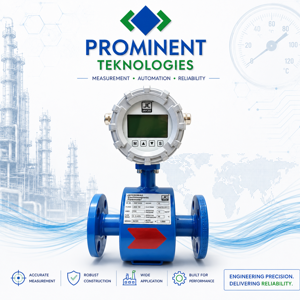
What is an Electromagnetic Flow Meter?
An electromagnetic flow meter, also called a mag flow meter, measures the volumetric flow of electrically conductive liquids using Faraday's Law of Electromagnetic Induction.
The meter creates a magnetic field across the measuring tube. When a conductive liquid moves through the field, an electrical potential difference is induced across the liquid. The electrodes detect this voltage, and the transmitter converts it into liquid velocity and volumetric flow rate.
Typical applications
Water, wastewater, conductive chemicals, effluent, many slurries, cooling water and process water.
Generally unsuitable
Gases, steam and most non-conductive oils/hydrocarbons.
3D Cross Section & Main Parts
Use a short 3D cutaway video to reveal the meter's internal parts step by step.
1. Transmitter
Excites the coils and processes the electrode signal.
2. Magnetic Coils
Create the magnetic field across the measuring tube.
3. Flow Tube + Liner
Carry and electrically isolate the conductive liquid.
4. Electrodes
Sense the induced voltage generated across the liquid.
5. Flanges
Connect the meter to the process pipeline.
6. Ground / Earth Rings
Provide a stable electrical reference where required.
How Magnetic Flux Produces an Induced EMF
1. The transmitter energizes the magnetic coils.
2. A magnetic field is established across the measuring tube.
3. Conductive liquid flows through the field.
4. The moving conductive liquid crosses the magnetic flux.
5. An EMF develops across the liquid.
6. Electrodes sense the voltage and the transmitter converts it into flow.
Laminar, Transitional & Turbulent Flow
Laminar Flow
Approx. Re < 2300
Smooth, orderly layers. The velocity profile can be strongly shaped across the pipe, so low-flow and straight-run guidance is important.
Transitional Flow
Approx. Re 2300–4000
The flow may alternate between laminar-like and turbulent behaviour and can be less predictable.
Turbulent Flow
Approx. Re > 4000
Random eddies and mixing are present. Many industrial mag meters operate very well here when the velocity profile is sufficiently developed.
Reynolds Number Calculator
Flow Rate & 4–20 mA Calculators
Flow Rate Calculator
4–20 mA Output Calculator
Installation Conditions for Reliable Reading
DO'S ✓
- Install where the measuring tube remains completely full.
- Provide proper grounding / bonding as required.
- Follow the selected manufacturer's straight-run guidance.
- Use the recommended electrode orientation.
- For slurry service, consider upward vertical flow where suitable.
- Check conductivity, liner and electrode compatibility.
DON'TS ✕
- Do not install at a high point where air can collect.
- Do not operate with a partially filled measuring tube.
- Do not ignore grounding requirements.
- Do not install immediately after pumps, valves or multiple elbows without checking the manual.
- Do not allow heavy deposits or electrode coating to build up unchecked.
Where Electromagnetic Flow Meters Are Commonly Used
💧 Water & Wastewater
Raw water, treated water, sewage, effluent and utilities.
🏭 Chemical Industry
Conductive chemicals where liner and electrode materials are compatible.
📄 Pulp & Paper
Process water and conductive slurry applications.
⚡ Power Plants
Cooling water and utility flow measurement.
⛏️ Mining & Minerals
Slurry and process-water applications.
🥛 Food & Beverage
Conductive liquids with suitable hygienic construction.
💊 Pharmaceutical
Conductive process liquids and utilities where hygienic requirements are satisfied.
🏗️ Industrial Utilities
Cooling water, process water and plant utility measurement.
Watch How an Electromagnetic Flow Meter Works
See the magnetic field, conductive liquid movement, induced EMF and electrode sensing as a simple animated sequence.
▶ Watch Video View Web Animation